Thursday, May 25, 2017

Sharing the Sunflower Galaxy M63 with Friends

Last night was the third night in a row to be in the obs... quite a record as of late!
We have had the pleasure of having some friends visit the past week and do last night I took them out to the obs and we did some star-gazing.
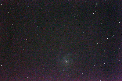
Since I can count on my Meade LX200GPS and my old XP laptop with the Meade AstroStar Suite software to work together accurately, we did some quickie astrophotography. The evening's favorite was the Sunflower Galaxy in Canes Venatici.
We took about 12 images at ISO 6400 with the average exposure time of 35 seconds with the LX200GPS with the Meade focal reducer. The camera was a Canon T2i operated by the Canon EOS utility. The focus was a bit soft, but I was just trying to give them an idea of what I do in the obs.

This is a cropped view:
Sunflower Galaxy aka M63

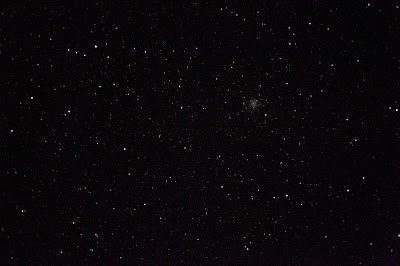
Here is the full frame image. As you can see it was off-centered. Again this was just a quick demo. I will return to it later and give it my full attention.


Tuesday, May 23, 2017

Testing, Testing... Meade LX200GPS 8" controlled with PC software

Well, at long last, the skies have pretty much cleared (as it ought to be in late May) giving me more opportunities (which have been precious little since the first of November 2016) to get into the observatory (hence, "obs") and practice with the Meade 8" LX200GPS upon its equatorial wedge mount AND with the Meade Autostar software running on a old Dell laptop (with a serial port) using Windows XP (which I keep independent from the internet for security reasons).

Having lined up the scope on the equatorial wedge to be fairly true to the north celestial pole (not the "Pole Star" Polaris because it is close to but not at the actual reference point on the starry background that the sky appears to rotate about) I proceeded to start up the scope and then the laptop with the Autostar software, connect the two via the needed cable, sent the telescope to a known star, centered it with the hand controller (which is, for some reason acting up as of late) then confirmed the star in the software.

From there... it was smooth (star) sailing!

I used the software to point the telescope to desired objects, and with the focal reducer in place, every (and I mean EVERY) object was in the field of view with my 40mm eyepiece!

AWESOME!

In just a few minutes I have viewed dozens of galaxies, star clusters and nebula.
Given that I was only out to test the setup and had accomplished that, I decided to do a little astrophotography.

And once again, with my Canon T2i camera body attached to the telescope and the focal reducer EVERY object I desired was in the field of view!

DOUBLY AWESOME!

Here are some samples.
NOTE: I was not trying for any kind of pro shots, just "quickies" as I verified that the scope and software were working well together. As a result the images have a lot of "grain" in them.
Most were taken at ISO 3200 and for 30 second exposures.
But I submit them for you viewing pleasure all the same! All are presented "full frame" (no cropping)

Two galaxies from the "Leo Triplet": M66 and M65

The Sombero Galaxy (M104)

(I forgot to log the info on this one, opps)

(and I forgot to log the info on this one, too... hey, I was just glad,
ok, surprised that it was there at all !)

M64 "The Black Eye Galaxy" 
(yes, that is what is referred to as!)

M13 The Great Globular Cluster in the constellation Hercules

M92

M57  The Ring Nebula in Lyra

M52 A loose cluster of stars

M101 The Pinwheel Galaxy
(near the handle of the "Big Dipper" aka Ursa Major
aka the Big Bear, etc)

M51 The Whirlpool Galaxy

I am looking forward to more clear nights and more practice! Stay tuned!


Thursday, May 18, 2017

The Citizen C.A.T.E. Project and First Light with Daystar telescope on The Sun

THE CITIZEN C.A.T.E. EXPERIMENT:
I am a primary participant in the Citizen C.A.T.E. (Continental-America Telescopic Eclipse) Experiment.

This n attempt to image the inner corona of the Sun during the August 21, 2017 solar eclipse. Typically scientists have only 2 to 3 minutes to image (video in particular) this portion of the Sun during an eclipse. The C.A.T.E. project aims to establish over 60 sites spread across the U.S.A. (from Oregon to South Carolina) Here is a map showing the path over Oregon:


At set distances apart, with identical equipment, to HDR (high dynamic range) video the eclipse at totality, like this image:


The video files will be sent to Matt Penn at the National Solar Observatory (NSO) after the event where they will be stitched together to (hopefully) produce up to 90 minutes of video totality for scientists to study.

MY INVOLVEMENT:
I first heard about this project in the January 2016 edition of Sky and Telescope magazine.

Being an amateur astronomer and wanting to do something "significant" scientifically, this intrigued me and I "signed up" immediately. I had the opportunity to be a 'state coordinator' but my schedule is busier than I could handle so I deferred to a fellow Oregonian who is retired, Mike Conley of Salem, Oregon, who had done an excellent job in helping the project.

MY SITE #5 - MITCHELL, OREGON:
My site for this project is outside the little village of Mitchell, Oregon which is on the eastern side of the state. I had hoped to setup on the grounds of the Painted Hills (part of the John Day Fossil Beds National Monuments.

But was informed by the ranger there that they are expecting untold 10's of thousands of people on that weekend because of the eclipse! A little two lane road and no parking... YIKES!

So I went to Mitchell, Oregon last August, 2016 to see if I could setup there.

As you can see, it is just a wide spot in the road, so to speak. But the only over-night places to stay were already booked... over a year in advance! Mitchell is expecting 10's of thousands as well which is going to be problematic again for I doubt it has even 50 places to park a car! Food, water, toilets for thousands... HA! Good luck on that, you who are thinking "This is the place to be!"
And the high school football field had been commandeered by emergency services (sheriff, paramedics, fire fighting government agencies, etc) as a helipad !

So I have found (hopefully) private property (location of which I will NOT disclose for obvious reasons) on which to accomplish this task.


THE EQUIPMENT:
The equipment for this project consists of, in short, a Daystar APO 80mm telescope on a Celestron CG4 mount with a Point Grey 5 megapixel b&w camera and a solar filter (more precise listing below).
No, that is not me in the photo but others being trained for this experiment.

Some of these pieces of equipment have been donated by various manufacturers and the rest has been financially supported by organizations like the National Science Foundation, NASA, Mathworks, Celestron (just to name a few) and as well as individuals who are purchasing their own equipment.

TRAINING:
Since the aim is to get video data worthy of science the C.A.T.E. Experiment (Continental-America Telescopic Eclipse) there is a need for quality training which is where the project is at the present time. Having received the equipment a couple of week ago, we are to do what we can to practice on the Sun and on the crescent Moon, working on field alignment, focus and data capturing.

My most recent PRACTICE:
As I have had little clear skies since receiving the equipment I have had little chance to practice until yesterday. Under partly cloudy skies (which even then were uncooperative) I was able to finally get the Sun in the clear to produce the following images. My goal was to image the tiny sunspot near the edge of the solar disk. After post-processing (sharpening, contrast and brightness, and sepia for effect) this is what I came up with (the second image is a cropped view).


And here is a shot of the Moon with the equipment (after post-processing)


A MORE DETAILED LIST OF THE EQUIPMENT
Telescope:
80mm diameter, 500mm focal length APO refractor from Daystar Filters
Solar filter, Thousand Oaks #S4250
Camera adapter, C-mount to 1.25", Baader/Agena, #2958515
Solar pointer, Sol Searcher

Mount and Drive:
Telescope mount, Celestron Omni CG4, #91509
Motor drive for CG4 Celestron #93522

Camera System:
5 Mpix CMOS camera, Point Grey GS3-U3-51S5M-C
GPIO Cable, Pt Grey, ACC-01-3000 (modifications needed)
USB3 Cable, Industrial Components.com #1673
USB2 Cable, Industrial Components.com, #UH2-2415
Arduino Uno, Rev 3, Mouser, #485-2877
Arduino Box, Karlsson Robotics, #PRT-10088
GPS Antenna, Banana Robotics, #BR010312
GPS Shield Board, ITEAD RoyalTek, #IM120417017 (modifications needed)
Arduino Jumper Cables, RobotShop, #RB-Dfr-353 (modifications needed)
Long female pin socket connector ICstation.com # 5831 (modifications needed)

Control Computer:
Core i5 laptop, 8Gby RAM, 256Gb SSD: Acer Aspire E15 E5-575G-527J #NX.GHHAA.004
8 Gb RAM, Ballistic/Amazon #BLS8G4S240FSD (must be installed in laptop)
32 Gb USB Drive, Amazon/San Disk, #CZ48
Laptop external power


 a Celestron CG-4 GEM mount & tripod, a simple RA/DEC motor system, a Daystar 80mm short-tube telescope, 

Monday, May 15, 2017

Adjusting RA Tension (tightness/looseness) on a Celestron OMNI XLT CG-4 German Equatorial Mount (GEM)

The mount I received from Celestron was overly tight in both DEC (declination) and RA (right ascension).

The problem with a tight mount is that you cannot properly balance the OTA (optical telescope assembly aka the telescope) and the result is that it places too much torque on the RA motor (for example) and will make it harder for the motor to track properly the motion of the stars across the night sky.

Finding precious little into on the web, I decided to put together a step-by-step instructional blog post to help my fellow astronomers who are having either a tightness problem or a looseness problem.

WARNING: You will likely VOID your warranty with Celestron if you attempt this fix. Just saying...
As for me, there is precious little to worry about. But proceed at your own risk.

***** First of all, remove the telescope from the mount so that you will not have it swinging around and potentially damaging both it and the mount needlessly.

The following instructions are for loosening or tightening the RA portion of the mount.
(DEC adjustments will be found HERE)

1. Tighten both the DEC knob and the RA knob and REMOVE all the counterweights but one (preferably leaving the lightest one on the long rod)
         WARNING: if you have the Celestron motor kit already attached to the mount
                      be sure to disconnect the RA gears from the motor (see your instruction manual)
                      just to be on the safe side.
                      If you do not do this you could ruin your RA motor while making this
                      adjustment.

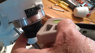
2. At the back end of the RA axis you will likely have white plastic cover that slips on the RA circles area. Remove it.

3. You likely find three finger screws on the black portion. Remove them. And if you have a polar scope, remove it at this time. (Screws were removed for this photo)
4. Now we enter a fork in the road. If you have one of these rubber strap tools (Harbor Freight


...it just may be that you will be able to strap it on to the black portion
AND HOLDING the counterweight shaft FIRMLY,
TWIST the black portion COUNTER-clockwise and the entire part including the dial attached to it should be able to unscrew from the housing.


If however you don't have one of these tools... GET ONE !  
You could use a wrench or pliers but you risk really scratching it up (or worse!)
Your choice, your risk !

Remove the black housing:

5. Loosen the RA dial knob and remove the upper RA dial cylinder.

6. This will expose a metal disk that has two indentations on it:

7. Now comes the hard part: This disk is what holds the RA axis in place AND is where you adjust the tension on the RA axis. To turn this you MIGHT be able to use two nails or Allen wrenchs to twist the disk (if it is loose enough) OR you will need to construct a tool like I had to (because mine was WAY TOO tight).
     The holes are 1 9/16" apart.
     I took a small piece of 2x4, and near the end of it drilled two holes just sufficient to tap in
     two nails whose points would fit into those indents. (Personally, I drilled a little deeper into
     the disk, taking care NOT to drill too deep or to leave metal fragments in the housing).


Then I inserted the nails into the holes (notice that there is a black pipe with threads that you will have to adjust the depth of the nails to clear).

8. Now loosen and remove the back RA latitude adjustment "screw". This will allow your mount to be parallel to the floor making attaching your tool and the adjustment to the RA tightness easier.

Lower the head until it is parallel to the floor.


9. RELEASE the RA lock knob AND HOLD the counterweight still with your free hand and attempt to twist the disk with your homemade tool to tighten (clockwise) or loosen (counter-clockwise) the disk.

NOTE: It will NOT take very much to change the tension! Be careful not to overdo it !


Test the looseness/tightness of the mount by swinging the counter-weight shaft back and forth.

    (As mine was really tight it took several attempts to twist it and in the end even when I didn't
      think I had done anything, there was a sufficient looseness that made me happy)

10. Now LOCK the RA lock knob. It is time to adjust the tension on the RA lock knob.


Using a Phillips screwdriver, remove the screw and knob. This will expose a square bolt.

At this point you may want to adjust the grip on the RA axis with this bolt. Using a 1/2" wrench, loosen the bolt a little (if it is overly tight) or tighten it (if your RA lock knob wasn't tight enough to hold the telescope in position.) Again, it will not take much to change the tension.


11. Reposition the RA black knob so that it is in a good position to loosen and tighten the RA then replace the Phillips screw.

12. Now slide the RA circle back in and lock it with the thumb screw


13. Screw the black housing for the polar scope back into the rear end of the mount. 
     Note: If you have a polar scope, now replace it in the black housing as per its instructions.

14. Replace the thumb screws that hold the polar scope in place

15. Replace the white housing cover
 
16. Now reassemble the mount and telescope as per normal including the counter-weights, RA motor shaft, OTA etc as needed... (see its instructions if necessary)